 |
 |
CLOSE , GET_GRAPHICS_FUNCTION , GET_WRITE_MASK , SET_CHARACTER_SIZE , SET_COLORS , SET_GRAPHICS_FUNCTION , SET_RESOLUTION , Z_BUFFERING
The IDL Z-buffer device is a pseudo device that draws 2D or 3D graphics in a buffer contained in memory. This driver implements the classic Z buffer algorithm for hidden surface removal. Although primarily used for 3D graphics, the Z-buffer driver can be used to create 2D objects in a frame buffer in memory. The resolution of this device can be set by the user.
All of the IDL plotting and graphics routines work with the Z-buffer device driver. In addition, the POLYFILL procedure has a few keyword parameters, allowing Gouraud shading and warping images over 3D polygons, that are only effective when used with the Z-buffer.
When used for 3D graphics, two buffers are present: an 8-bit-deep frame buffer that contains the picture; and a 16-bit-deep Z-buffer of the same resolution, containing the z-value of the visible surface of each pixel. The Z-buffer is initialized to the depth at the back of the viewing volume. When objects are drawn, the z-value of each pixel is compared with the value at the same location in the Z-buffer, and if the z-value is greater (closer to the viewer), the new pixel is written in the frame buffer and the Z-buffer is updated with the new z-value.
The Z-buffer device is a "pseudo device" in that drawing commands update buffers in memory rather than sending commands to a physical device or file. The TVRD function reads the contents of either buffer to an IDL array. This array may then be further processed, written to a file, or output to a raster-based graphics output device.
The Z-buffer driver can be used for 2D graphics by disabling the depth computations.
To use the Z-buffer as the current graphics device, issue the IDL command:
Once the Z-buffer driver is enabled the DEVICE procedure is used to control its actions, as described below.
to view the current state of the Z-buffer driver and the amount of memory used for the buffers.
The contents of both buffers are directly accessed by the TV and TVRD routines. The frame buffer that contains the picture is 8 bits deep and is accessed as channel 0. The Z depth buffer contains 16 bit integers and is accessed as channel 1. Always use CHANNEL=1 and set the keyword WORDS when reading or writing the depth buffer.
The normal procedure is to set the graphics device to "Z", draw the objects, read the frame buffer, and then select another graphics device and write the image. For example, to create an image with the Z-buffer driver and then display it on an X-Window display:
SET_PLOT,'Z' ; Select Z-buffer device.
... ... ... ; Write objects to the frame buffer using normal graphics routines, e.g. PLOT, SURFACE, POLYFILL.
a=TVRD() ; Read back the entire frame buffer.
SET_PLOT,'X' ; Select X Windows.
TV, a ; Display the contents of the frame buffer.
To read the depth values in the Z-buffer, use the command:
To write the depth values, use the command:
The TV, TVSCL, and TVRD routines write or read pixels directly to a rectangular area of the designated buffer without affecting the other buffer.
The values in the depth buffer are short integers, scaled from -32765 to +32765, corresponding to normalized Z-coordinate values of 0.0 to 1.0.
The following POLYFILL keywords are active only with the Z-buffer device: IMAGE_COORDINATES, IMAGE_INTERPOLATE, and TRANSPARENT. These parameters allow images, specified via the PATTERN keyword, to be warped over 2D and 3D polygons.
The IMAGE_COORDINATES keyword contains a 2 by N array containing the image space coordinates that correspond to each of the N vertices of the polygon. The IMAGE_INTERPOLATE keyword indicates that bilinear interpolation is to be used, rather than the default nearest neighbor sampling. Pixels less than the value of TRANSPARENT are not drawn, simulating transparency. For Gouraud shading of polygons, the COLOR keyword can contain an array specifying the color index for each polygon vertex.
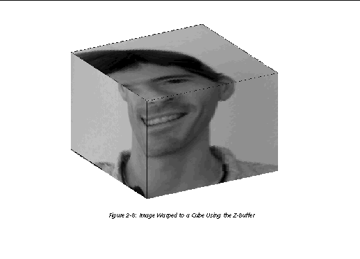
This example forms a Bessel function, draws its shaded surface and overlays its contour, using the Z-buffer as shown in Image Warped to a Cube Using the Z-Buffer ; The final output is directed to PostScript.

SET_PLOT, 'Z' ; Select the Z-buffer.
n = 50 ; Size of array for Bessel.
a = BESELJ(SHIFT(DIST(n), n/2, n/2)/2, 0)
;
Make the Bessel function.
SHADE_SURF, a, /SAVE, COLOR=1, BACKGROUND=255
;
Draw the surface, label axes in black, background in white.
nlev = 8 ; Number of contour levels.
CONTOUR, a, /OVERPLOT, ZVALUE=.6, /T3D, $
LEVELS=FINDGEN(nlev)*1.5/nlev-.5, COLOR=1
;
Make the Contour at normalized Z=.6.
SET_PLOT, 'PS' ; Select PostScript output.
DEVICE, /CLOSE ; Close the new PostScript file.
The following example warps an image to a cube as shown in Image Warped to a Cube Using the Z-Buffer . The lower two quadrants of the image are warped to the front two faces of the cube. The upper-right quadrant is warped to the top face of the cube. The image is held in the array a , with dimensions nx by ny .
SET_PLOT, 'Z' ; Select the Z-buffer.
ERASE, 255 ; Make a white background for final output to PostScript.
SCALE3, XRANGE=[0,1], YRANGE=[0,1], ZRANGE=[0,1]
;
Establish 3D scaling as (0,1) cube.
verts = [[0,0,0], [1,0,0], [1,1,0], [0,1,0], $
[0,0,1], [1,0,1], [1,1,1], [0,1,1]]
;
Define vertices of cube. Vertices 0-3 are bottom, 4-7 are top.
POLYFILL, verts[*, [3,0,4,7]], /T3D, PATTERN=a, $
IMAGE_COORD=[[0,0], [nx/2,0], [nx/2,ny/2], [0,ny/2]]
;
Fill lower left face.
POLYFILL, verts[*, [0,1,5,4]], /T3D, PATTERN=a, $
IMAGE_COORD=[[nx/2,0], [nx-1,0], $
[nx-1,ny/2], [nx/2,ny/2]]; Lower right face.
POLYFILL, verts[*, [4,5,6,7]], /T3D, PATTERN=a, $
IMAGE_COORD = [[nx/2,ny/2], [nx-1,ny/2], $
[nx-1,ny-1], [nx/2,ny-1]]; Top face.
PLOTS, verts[*, [0,4]], /T3D, COLOR=0; Draw edges of cube in black.
PLOTS, verts[*, [4,5,6,7,4]], /T3D, COLOR=0
;
Edges of top face.
The image is then output to PostScript as in the previous example.
